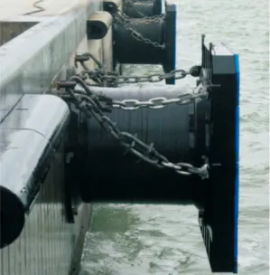
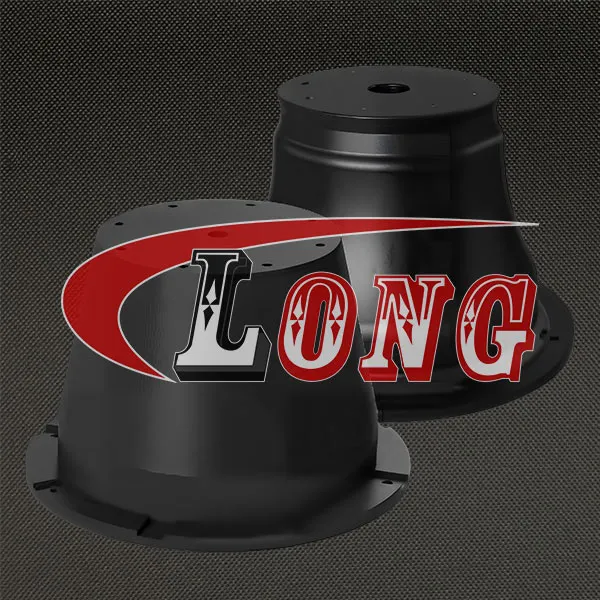
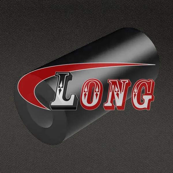
LGRIG® Super Cell Rubber Fenders SCA Type, also known as Cell Fender, or Cell Rubber Fender.
Cell fenders are some of the most popular fenders in use today, with a unique circular shape that grants superior stability compared to similar large fenders, available in outer diameters ranging from 650mm to 3000mm and a variety of lengths to match your application.
Super cell rubber fender offers one of the highest energy absorption to weight ratios of any fender, enabling use in both large and small scale applications with excellent versatility.
LGRIG® Super Cell Rubber Fenders distribute impact pressure and weight easily thanks to their circular shape, providing superior impact absorption and prolonging fender life.
Cell rubber fender features the lowest compression performance change among compression fenders, maintaining impact absorption and resistance rates regardless of vessel weight. Customers can also install UHMW-PE-ECO sliding fender plates on these cell fenders to further increase life expectancy by reducing friction and hull pressure.
Cell fenders are best employed for large-size vessels where higher energy and lower reaction are critical, with a basic design that gives sturdiness, shear resistance, and the ability to absorb energy equally from all directions.
The cylindrical buckling column of a super cell rubber fender absorbs axial loads effectively and buckles radially, and these fenders are equipped with frontal frames having low friction fascia pads to reduce shear force and hull pressure. Cell rubber fenders can be installed in single, dual, or multiple combinations with a common frontal frame for optimized performance, and the facility to fit long frames provides a larger vertical or horizontal contact area for ports with huge tidal variation.
Super cell rubber fender is one of the most proven and reliable marine fender styles ever designed, historically the most commonly used in the industry, originally created to replace cylindrical fenders with over 30 years of proven performance. These cell fenders are designed to absorb collision energy between ship and dock during berthing for berths, dolphin wharfs, offshore docks, and terminals, with large mounting flanges that distribute loading over the fender panel frame and allow easy installation.
LGRIG® super cell rubber fenders are available in the widest range of sizes of any fender type, providing high quality at competitive prices, with key advantages including high energy absorption for large vessels and high-traffic berths, low reaction force protecting both vessel and quay structure, excellent durability against UV and saltwater, and a long service life of more than 10 years with proper maintenance.

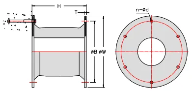
Part No. | Specification | H | T | φB | φW | Φd | Anchors | Weight /Kg |
LGCF500H | 500H | 500 | 25 | 550 | 650 | 32 | 4-M24 | 112 |
LGCF630H | 630H | 630 | 30 | 700 | 840 | 39 | 4-M30 | 231 |
LGCF800H | 800H | 800 | 30 | 900 | 1050 | 40 | 6-M33 | 410 |
LGCF1000H | 1000H | 1000 | 35 | 1100 | 1300 | 47 | 6-M39 | 822 |
LGCF1150H | 1150H | 1150 | 40 | 1300 | 1500 | 50 | 6-M42 | 1220 |
LGCF1250H | 1250H | 1250 | 45 | 1450 | 1650 | 53 | 6-M45 | 1488 |
LGCF1450H | 1450H | 1450 | 47 | 1650 | 1850 | 61 | 6-M52 | 2330 |
LGCF1600H | 1600H | 1600 | 50 | 1800 | 2000 | 61 | 8-M52 | 3022 |
LGCF1700H | 1700H | 1700 | 55 | 1900 | 2100 | 66 | 8-M56 | 3730 |
LGCF2000H | 2000H | 2000 | 55 | 2000 | 2200 | 74 | 8-M64 | 5258 |
LGCF2250H | 2250H | 2250 | 60 | 2300 | 2550 | 74 | 10-M64 | 7452 |
LGCF2500H | 2500H | 2500 | 70 | 2700 | 2950 | 74 | 10-M64 | 10755 |
LGCF3000H | 3000H | 3000 | 85 | 3150 | 3350 | 90 | 12-M76 | 18582 |
Unit: mm
No. | Description | Application | Material | |
1 | Rubber Fender | Absorb ship impact energy to protect dock and vessels | Rubber,Q235 | |
2 | Cast-in | Precast Nut & | For fender fixing to dock | Stainless Steel, |
U Anchor | Holding chains | Q235 Painted(or HDG) | ||
3 | Frontal Panel | Bear the force caused by fender buffer, increase the contact area with ship and lessen hull pressure. | Q235/Q355 Painted(or hot | |
4 | Facing Pad | Reduce friction coefficient to protect hull | UHMW-PE | |
5 | Bolt &Nut | For fender fixing to Front panel or other | Stainless Steel, | |
6 | Chain System | Weight Chain | Support the steel panel and prevent excessive drooping of the system | Q235,CM490 HDG or |
Tension Chain | Limit fenders deflection while fender local part under strain | Q235,CM490 HDG or | ||
Shear Chain | Prevent fenders system from shear deflection | Q235,CM490 HDG or | ||
Minimum Clearances
There must be enough space around and between the cell fenders and the steel panel to allow them to deflect without interference.
Specification | Edge(A) | Centres(B) |
500H | 510 | 700 |
630H | 600 | 880 |
800H | 700 | 1120 |
1000H | 850 | 1500 |
1150H | 990 | 1730 |
1250H | 1060 | 1870 |
1450H | 1200 | 2180 |
1600H | 1270 | 2400 |
1700H | 1470 | 2550 |
2000H | 1560 | 2880 |
2250H | 1710 | 3360 |
2500H | 1910 | 3730 |
3000H | 2240 | 4500 |
Unit: mm
Specification | 500H | 630H | 800H | 1000H | 1150H | 1250H | 1450H | 1600H | 1700H | 2000H | 2250H | 2500H | 3000H | ||
Performance | |||||||||||||||
RE | 52.5% | R | 182 | 290 | 464 | 737 | 975 | 1153 | 1551 | 1885 | 2131 | 2941 | 4145 | 5118 | |
E | 40 | 80 | 163 | 324 | 492 | 632 | 987 | 1326 | 1591 | 2591 | 4095 | 5618 | |||
55% | R | 210 | 309 | 493 | 784 | 1037 | 1225 | 1649 | 2007 | 2266 | 3136 | 4406 | 5441 | ||
E | 43 | 85 | 173 | 343 | 521 | 669 | 1045 | 1405 | 1685 | 2743 | 4337 | 5949 | |||
RS | 52.5% | R | 162 | 258 | 412 | 655 | 865 | 1022 | 1376 | 1676 | 1892 | 2619 | 3679 | 4543 | |
E | 36 | 72 | 145 | 287 | 437 | 561 | 876 | 1177 | 1413 | 2300 | 3628 | 4987 | |||
55% | R | 187 | 274 | 437 | 696 | 920 | 1087 | 1464 | 1781 | 2012 | 2783 | 3911 | 4829 | ||
E | 38 | 76 | 153 | 304 | 463 | 594 | 928 | 1247 | 1495 | 2435 | 3848 | 5280 | |||
RH | 52.5% | R | 140 | 224 | 355 | 567 | 750 | 886 | 1193 | 1453 | 1640 | 2270 | 3188 | 3937 | 5687 |
E | 30 | 62 | 125 | 249 | 379 | 486 | 760 | 1020 | 1224 | 1994 | 3150 | 4322 | 7456 | ||
55% | R | 160 | 237 | 378 | 603 | 798 | 942 | 1269 | 1544 | 1743 | 2413 | 3390 | 4182 | 6619 | |
E | 32 | 67 | 132 | 264 | 401 | 516 | 804 | 1080 | 1300 | 2111 | 3336 | 4576 | 7521 | ||
RO | 52.5% | R | 108 | 172 | 275 | 436 | 578 | 682 | 918 | 1120 | 1262 | 1746 | 2454 | 3028 | 4314 |
E | 23 | 47 | 96 | 191 | 295 | 375 | 585 | 786 | 945 | 1535 | 2425 | 3330 | 5676 | ||
55% | R | 125 | 182 | 292 | 463 | 614 | 725 | 976 | 1189 | 1342 | 1856 | 2607 | 3220 | 5099 | |
E | 25 | 50 | 102 | 203 | 309 | 396 | 619 | 832 | 997 | 1624 | 2566 | 3520 | 6028 | ||
RL | 52.5% | R | 86 | 138 | 211 | 349 | 462 | 546 | 735 | 894 | 1009 | 1398 | 2085 | 2574 | 3677 |
E | 18 | 38 | 75 | 153 | 233 | 299 | 468 | 628 | 753 | 1227 | 2060 | 2826 | 4897 | ||
55% | R | 99 | 147 | 225 | 372 | 491 | 581 | 781 | 950 | 1073 | 1485 | 2216 | 2737 | 4217 | |
E | 19 | 40 | 78 | 163 | 247 | 316 | 495 | 665 | 798 | 1299 | 2180 | 2992 | 5193 | ||
RE:Extreme high Reaction Force, RS:Super high Reaction Force, RH: High Reaction Force, RO:S tandard Reaction Force, RL:Low Reaction Force
R:Reaction Force,E:Energy Absorption;
Rated Deflection:52.5%, Maximum Deflection:55%
Performance tolerance: Reaction Force≤+10%,Energy Absorption≥-10%
PIANC factors | |||||
Angular compression Factor | Temperature Factor | Velocity Factor | |||
Angle(degree) | AF | Temperature(°C) | TF | Time(second) | VF |
0 | 1.000 | 50 | 0.882 | 1 | 1.005 |
3 | 0.977 | 40 | 0.926 | 2 | 1.002 |
5 | 0.951 | 30 | 0.969 | 3 | 1.001 |
8 | 0.909 | 23 | 1.000 | 4 | 1.001 |
10 | 0.883 | 10 | 1.056 | 5 | 1.000 |
15 | 0.810 | 0 | 1.099 | 6 | 1.000 |
20 | 0.652 | -10 | 1.143 | 8 | 1.000 |
-20 | 1.186 | ≥10 | 1.000 | ||
-30 | 1.230 | ||||
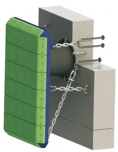
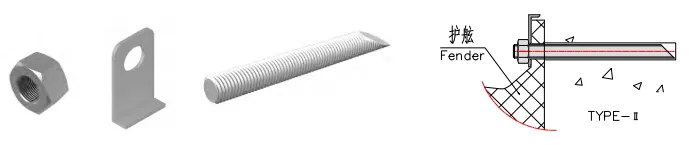
A cell fender system includes Rubber fender, frontal panel, facing pad, fasteners, anchors, chain systems, etc.


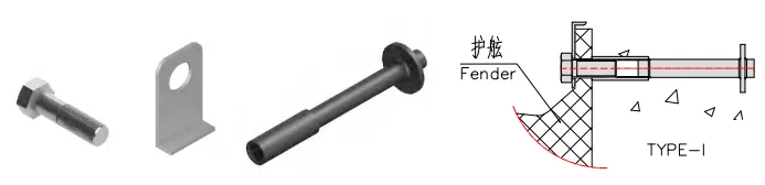
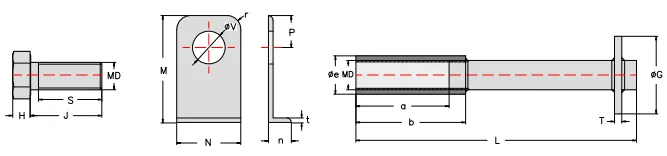
Used for installing fenders to new concrete.


Specification | Hex Bolt | L-Washer | Precast Nut | Anchor Rod,plate | |||||||||||||
MD | H | J | S | N | n | M | P | t | V | r | a | b | e | T | L | G | |
500H | M24 | 17 | 70 | 55 | 60 | 22 | 83 | 25 | 5 | 28 | 15 | 75 | 100 | 36 | 6-10 | 300 | 75 |
630H | M30 | 19 | 75 | 60 | 65 | 20 | 110 | 33 | 5 | 34 | 15 | 75 | 105 | 38 | 8-12 | 330 | 85 |
800H | M33 | 23 | 85 | 70 | 70 | 25 | 117 | 35 | 5 | 36 | 15 | 85 | 120 | 42 | 8-12 | 360 | 85 |
1000H | M39 | 26 | 95 | 75 | 80 | 26 | 148 | 40 | 6 | 43 | 25 | 85 | 125 | 49 | 8-12 | 430 | 95 |
1150H | M42 | 26 | 100 | 80 | 85 | 28 | 151 | 43 | 6 | 46 | 25 | 85 | 125 | 55 | 12-16 | 500 | 105 |
1250H | M45 | 30 | 110 | 90 | 90 | 31 | 153 | 45 | 6 | 49 | 30 | 95 | 140 | 59 | 12-16 | 500 | 125 |
1450H | M52 | 35 | 120 | 95 | 100 | 31 | 158 | 50 | 6 | 56 | 30 | 100 | 150 | 69 | 12-16 | 570 | 135 |
1600H | M52 | 35 | 120 | 95 | 100 | 34 | 158 | 50 | 6 | 56 | 30 | 100 | 150 | 69 | 12-16 | 570 | 140 |
1700H | M56 | 35 | 135 | 110 | 110 | 40 | 165 | 55 | 8 | 63 | 30 | 105 | 165 | 75 | 16-20 | 620 | 140 |
2000H | M64 | 40 | 150 | 125 | 116 | 38 | 165 | 58 | 8 | 70 | 40 | 125 | 190 | 79 | 16-20 | 700 | 150 |
2250H | M64 | 40 | 150 | 125 | 120 | 43 | 195 | 60 | 8 | 70 | 40 | 125 | 190 | 79 | 16-20 | 700 | 150 |
2500H | M64 | 40 | 170 | 125 | 125 | 50 | 202 | 65 | 10 | 70 | 50 | 125 | 190 | 79 | 16-20 | 700 | 175 |
3000H | M76 | 50 | 190 | 145 | 140 | 55 | 207 | 70 | 10 | 84 | 50 | 135 | 210 | 95 | 20-24 | 800 | 175 |
Unit: mm
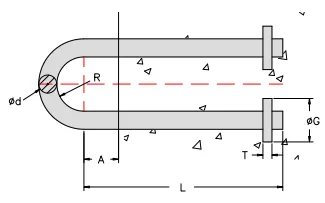
Used for installing fenders onto existing concrete or where precast nut are unsuitable.


Specification | Anchor Bolt | Nut | L-Washer | |||||||||
MD | A | L | φS | T | N | n | M | P | t | V | r | |
500H | M24 | 60 | 280 | 30 | 22 | 60 | 22 | 83 | 25 | 5 | 28 | 15 |
630H | M30 | 70 | 360 | 38 | 26 | 65 | 20 | 110 | 33 | 5 | 34 | 15 |
800H | M33 | 75 | 400 | 42 | 28 | 70 | 25 | 117 | 35 | 5 | 36 | 15 |
1000H | M39 | 85 | 460 | 50 | 32 | 80 | 26 | 148 | 40 | 6 | 43 | 25 |
1150H | M42 | 95 | 510 | 55 | 34 | 85 | 28 | 151 | 43 | 6 | 46 | 25 |
1250H | M45 | 105 | 550 | 60 | 36 | 90 | 31 | 153 | 45 | 6 | 49 | 30 |
1450H | M52 | 115 | 630 | 65 | 42 | 100 | 31 | 158 | 50 | 6 | 56 | 30 |
1600H | M52 | 115 | 630 | 65 | 42 | 100 | 34 | 158 | 50 | 6 | 56 | 30 |
1700H | M56 | 125 | 680 | 68 | 45 | 110 | 40 | 165 | 55 | 8 | 63 | 30 |
2000H | M64 | 130 | 780 | 75 | 51 | 116 | 38 | 165 | 58 | 8 | 70 | 40 |
2250H | M64 | 140 | 780 | 75 | 51 | 120 | 43 | 195 | 60 | 8 | 70 | 40 |
2500H | M64 | 150 | 780 | 75 | 51 | 125 | 50 | 202 | 65 | 10 | 70 | 50 |
3000H | M76 | 180 | 940 | 88 | 64 | 140 | 55 | 207 | 70 | 10 | 84 | 50 |
Unit: mm

Specification | Φd | R | L | A | T | ΦG |
500H | 40 | 70 | 600 | 50 | 20~30 | 100 |
630H | 40 | 70 | 600 | 50 | 20~30 | 100 |
800H | 50 | 80 | 650 | 50 | 20~30 | 110 |
1000H | 55 | 90 | 730 | 50 | 20~30 | 120 |
1150H | 60 | 100 | 780 | 50 | 25~35 | 140 |
1250H | 60 | 100 | 780 | 50 | 25~35 | 140 |
1450H | 60 | 100 | 780 | 70 | 25~35 | 140 |
1600H | 65 | 105 | 830 | 70 | 25~35 | 150 |
1700H | 65 | 105 | 830 | 70 | 25~35 | 150 |
2000H | 70 | 115 | 880 | 70 | 25~35 | 160 |
2250H | 70 | 115 | 880 | 70 | 25~35 | 160 |
2500H | 80 | 120 | 930 | 70 | 25~35 | 160 |
3000H | 80 | 120 | 930 | 80 | 25~35 | 160 |
Unit: mm

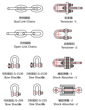
Specification | Links | Shackle | Tensioner |
500H | φ20.5 | φ22 | M24 |
630H | φ20.5 | φ22 | M24 |
800H | φ26 | φ28 | M30 |
1000H | φ28 | φ32 | M33 |
1150H | φ32 | φ35 | M36 |
1250H | φ34 | φ38 | M42 |
1450H | φ36 | φ38 | M42 |
1600H | φ38 | φ45 | M48 |
1700H | φ40 | φ45 | M48 |
2000H | φ42 | φ45 | M48 |
2250H | φ42 | φ45 | M48 |
2500H | φ46 | φ50 | M56 |
3000H | φ46 | φ50 | M56 |
Material | Q235 HDG, | Gr.S HDG | Q235/GR8.8 HDG |
There must be enough space around and between the cell fenders and the steel panel to allow them to deflect without interference.
Specification | Edge(A) | Centres(B) |
500H | 510 | 700 |
630H | 600 | 880 |
800H | 700 | 1120 |
1000H | 850 | 1500 |
1150H | 990 | 1730 |
1250H | 1060 | 1870 |
1450H | 1200 | 2180 |
1600H | 1270 | 2400 |
1700H | 1470 | 2550 |
2000H | 1560 | 2880 |
2250H | 1710 | 3360 |
2500H | 1910 | 3730 |
3000H | 2240 | 4500 |
Unit: mm
Cell fenders can support a lot of static weight.
The table is a guide to the permitted weight of front panel before additional support chains may be required.
Performance | Single or multiple | Multiple vertical | H |
RL | WH≤n×0.95×w | WV≤n×1.2×w | |
RO | WH≤n×1.1×w | WV≤n×1.45×w | H≤800 |
RH | WH≤n×1.3×w | WV≤n×1.75×w | |
RL | WH≤n×10×w0.6 | WV≤n×13.5×w0.6 | |
RO | WH≤n×15×w0.6 | WV≤n×19×w0.6 | H≥1000 |
RH | WH≤n×19×w0.6 | WV≤n×23.5×w0.6 |
n= number of Cell fenders.
W=Fender weight
WH=panel weight-single or multi-horizontal
WV=panel weight-single or multi-vertical